Greetings, in this article I will show you how to build a structure for network testing from scratch and then make the necessary adjustments. Have a good read.
Prerequisites
A PC
Minimum 8Gb Flash Drive
Router (x86_64): Zimaboard 832
Managed or Smart Switch: TP-Link TL-SG105E
Router (for WLAN): Xiaomi Mi Router 4 Giga Edition with OpenWRT
My conditions allow me to test with this hardware. If you have better ones, you can use them.
Router Configuration
In this section, I will not talk about OPNsense installation and initial settings, you can set it up as you wish.
The network I set up as an example:
LAN: 10.1.0.1/24
WAN: 192.168.1.210/24
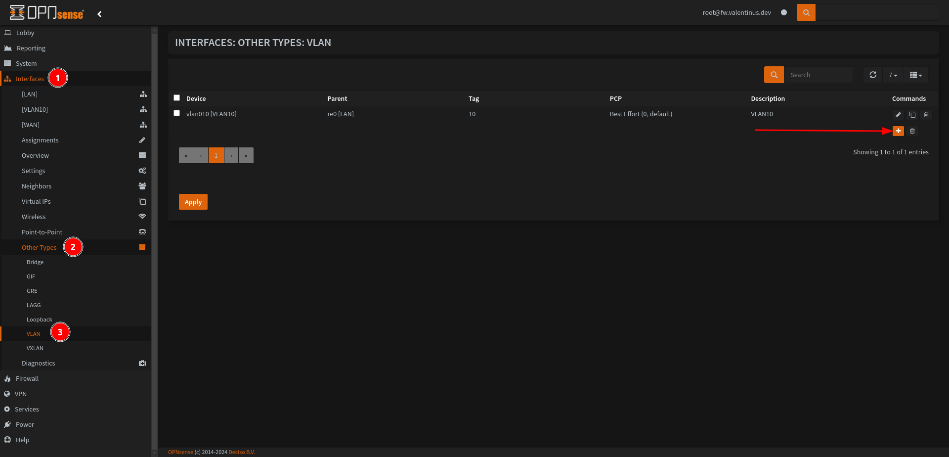
Create VLAN 10 with OPNsense
Go to Interfaces --> Other Types --> VLAN, you’ll see + icon under VLAN. Add VLAN10 with using it.
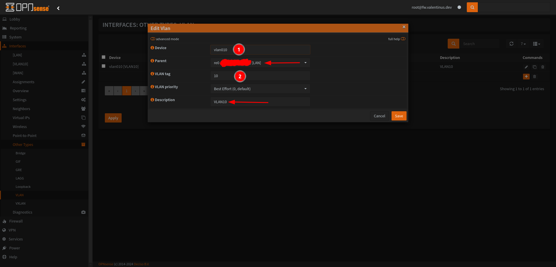
Set:
Device: vlan010
Parent: re0 [LAN]
VLAN tag: 10
Description: VLAN10
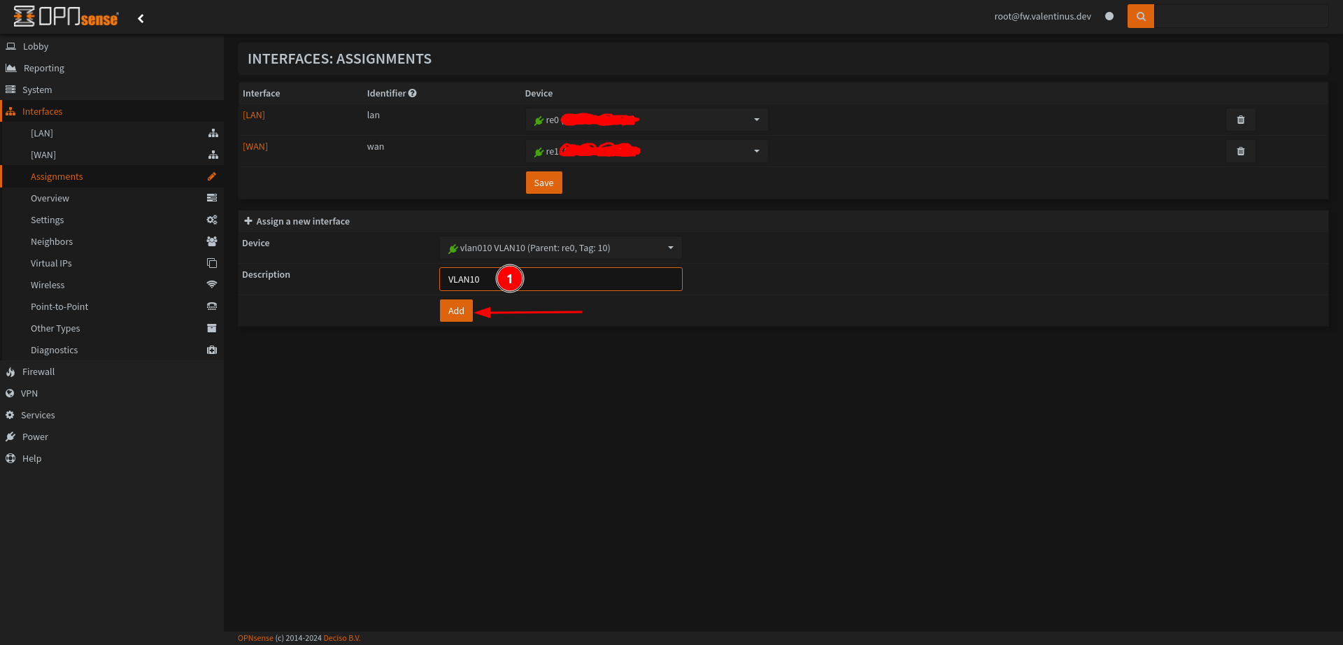
Assign VLAN 10 to Network and Start VLAN Interface
Come Interfaces --> Assignments then add VLAN10 interface
After, screen will look like this
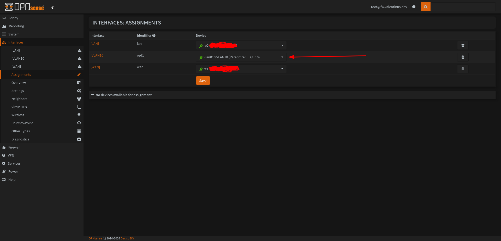
Now we have VLAN10 Interface, to enable VLAN10 interface go to Interfaces --> VLAN10 then enable it, then set IPv4 Configuration Type to Static IPv4 .
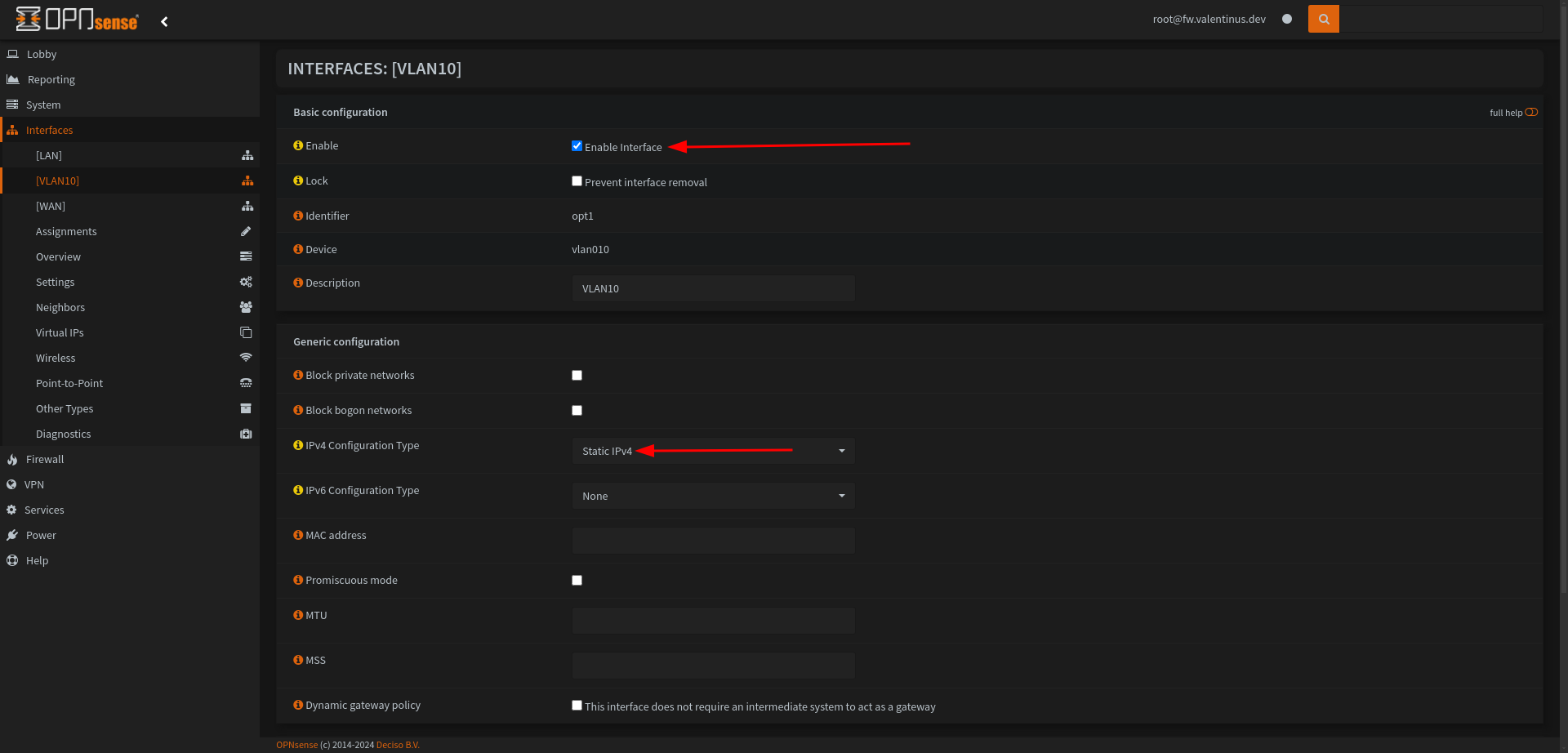
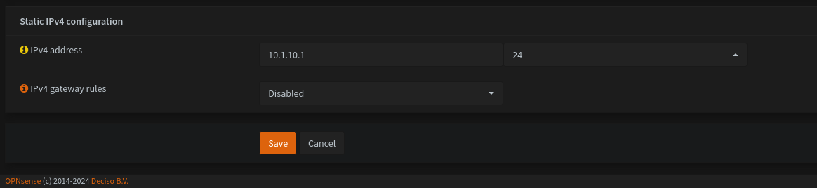
Come to under the page and set IPv4 Address to 10.1.10.1/24.
You can set it different too, my test network is 10.1.0.0/24 and open VLAN Network with different subnet for 10.1.10.0/24. (VLAN 10 and Subnet 10)
Don’t forget after click Apply Changes.
Firewall Rules for VLAN 10
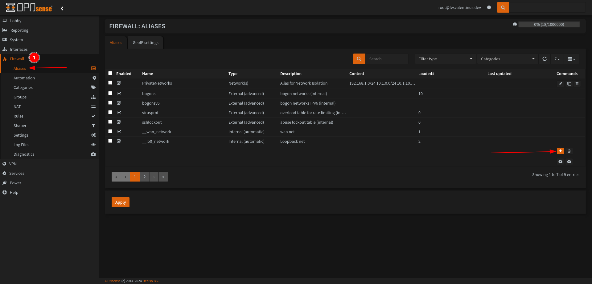
Before writing Rules for the Firewall, we create Alias for Private Networks (192.168.1.0/24, 10.1.0.0/24 and 10.1.10.0/24). If we don’t do this, we will enter 3 rules instead of 1 rule and it will be easier to find this way when we enter more rules in the future.
Firewall --> Aliases
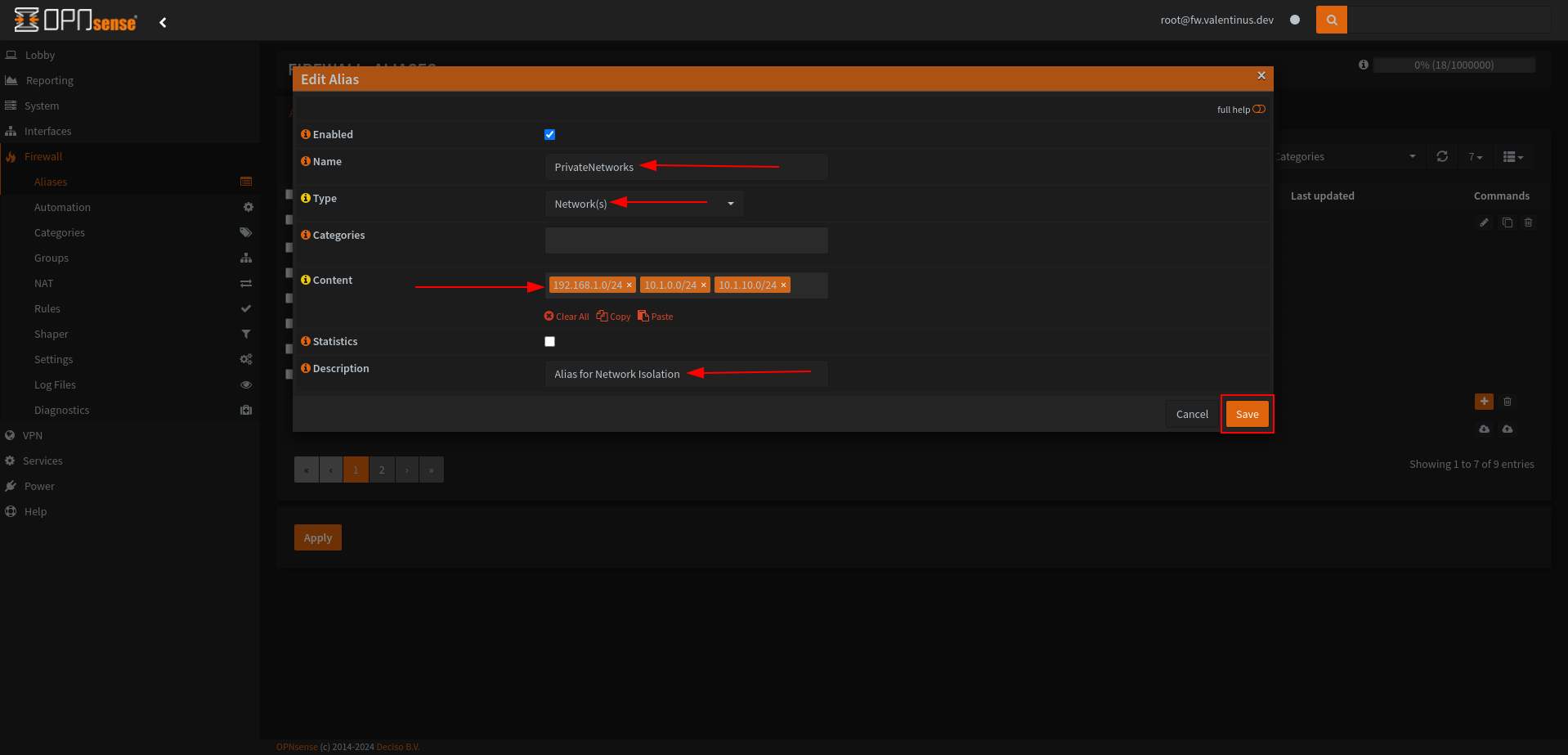
Name: PrivateNetworks
Type: Networks
Content: 192.168.1.0/24 + 10.1.0.0/24 + 10.1.10.0/24
Description: Alias for Network Isolation
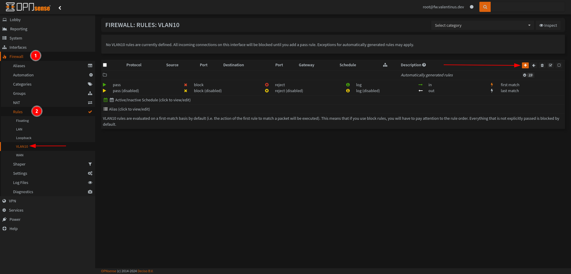
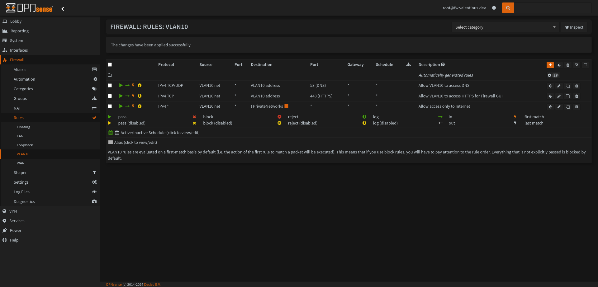
Then come to Firewall --> Rules --> VLAN10 and add this rules for network security.
| Action | TCP/IP Version | Protocol | Source | Dest / Invert | Destination | Dest Port | Description |
|---|---|---|---|---|---|---|---|
| Pass | IPv4 | TCP/UDP | VLAN10 net | unchecked | VLAN10 address | 53 | Allow VLAN10 to access DNS |
| Pass | IPv4 | TCP | VLAN10 net | unchecked | VLAN10 address | 443 | Allow VLAN10 to access HTTPS for Firewall GUI |
| Pass | IPv4 | any | VLAN10 net | checked | VLAN10 address | any | Allow access only to Internet |
It will see like this after all:
Don’t forget apply changes.
Enable DHCP for VLAN 10
We come to the last step of setting up the VLAN10 network, now we enable DHCP and finish the network setup by the Router.
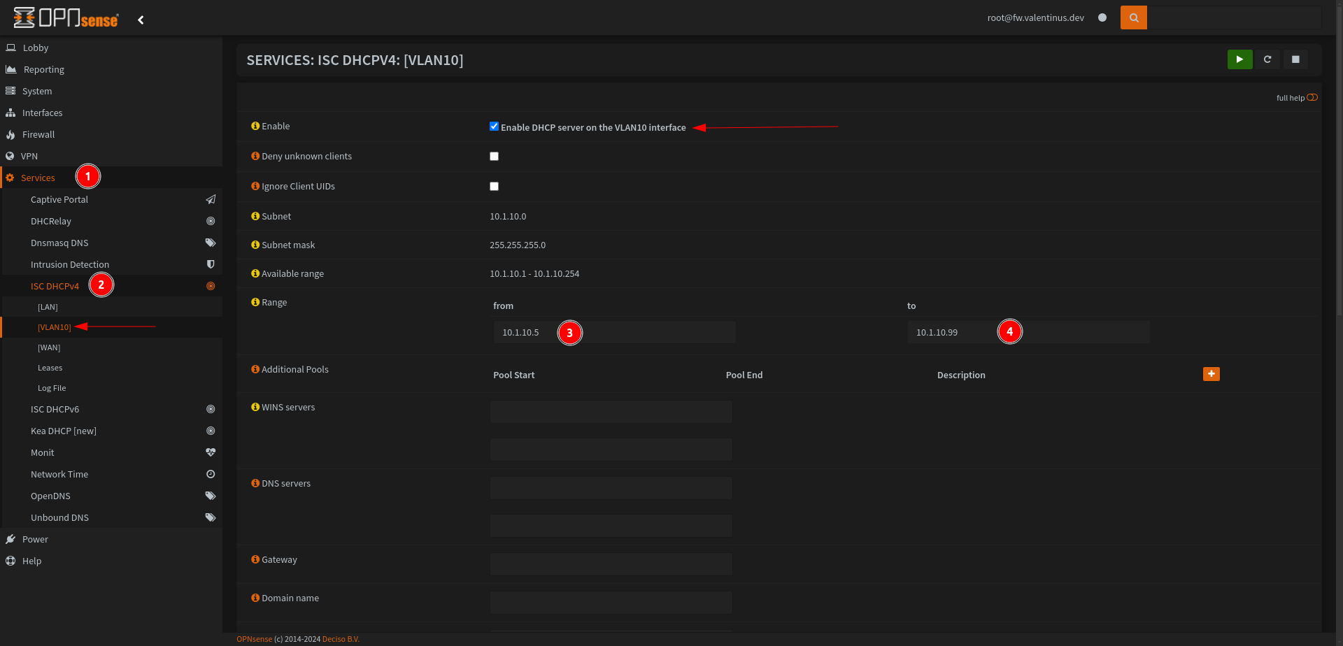
Don’t forget scroll down and save.
Configure Shaper for Bufferbloat
When I connected to the network, after a while I started to experience noticeable disconnections.
I thought it wasBufferbloat, so I ran a test and saw that theDownload Activeoutput was too high.
I ran the test 5 times andUpload Activestarted to rise unusually in between. When this happened, I started to avoid Bufferbloat.
I have 500 Mbit/s Up / 50 Mbit/s Down
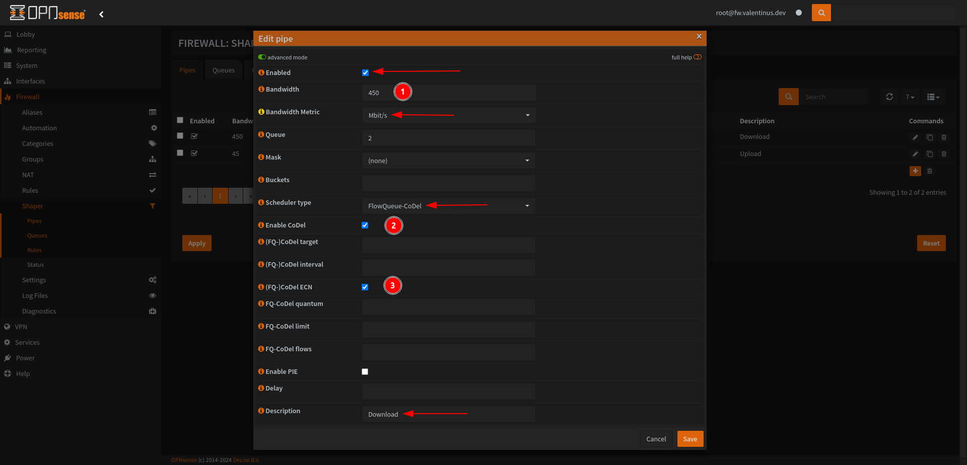
Set Pipes
Come to Firewall --> Shaper then add a shaper like as below.
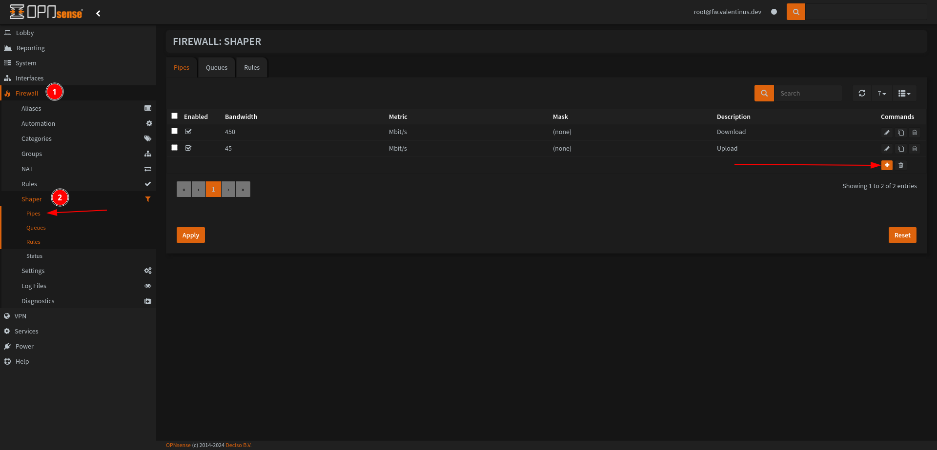 Set:
Set:
Enabled: Checked
Bandwidth: 450 (set whatever value works best for your network)
Bandwidth Metric: Mbit/s
Scheduler Type: FlowQueue-CoDel
Enable CoDel: Checked
(FQ-)Codel ECN: Checked
Description: Download or Download Shaper
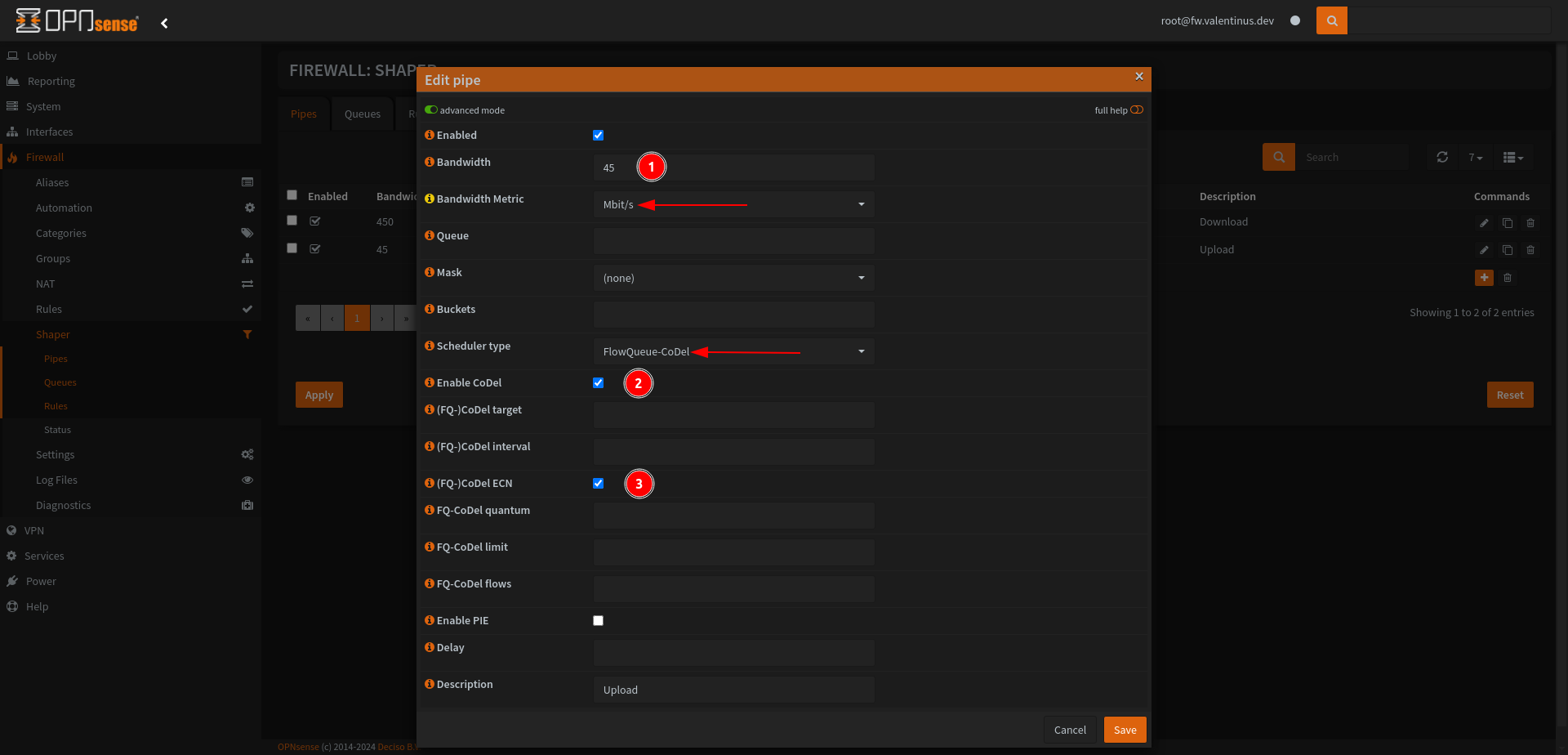
Next, apply the above process according to your upload speed.
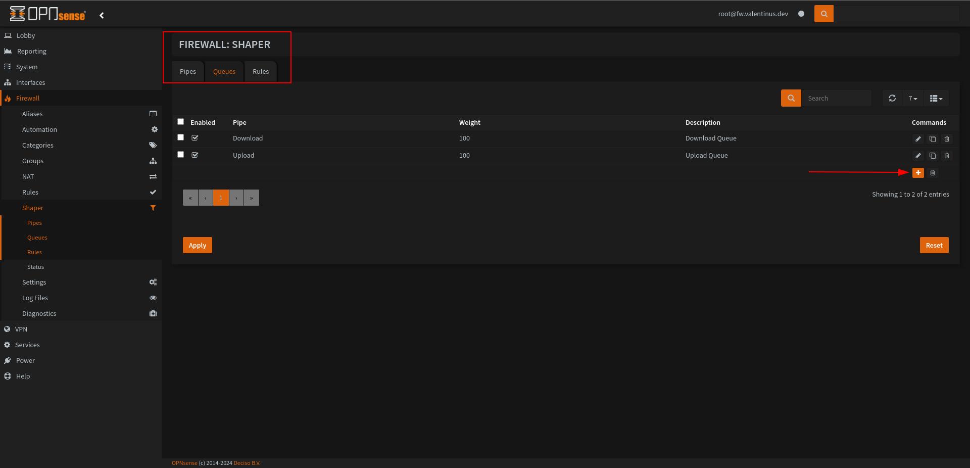
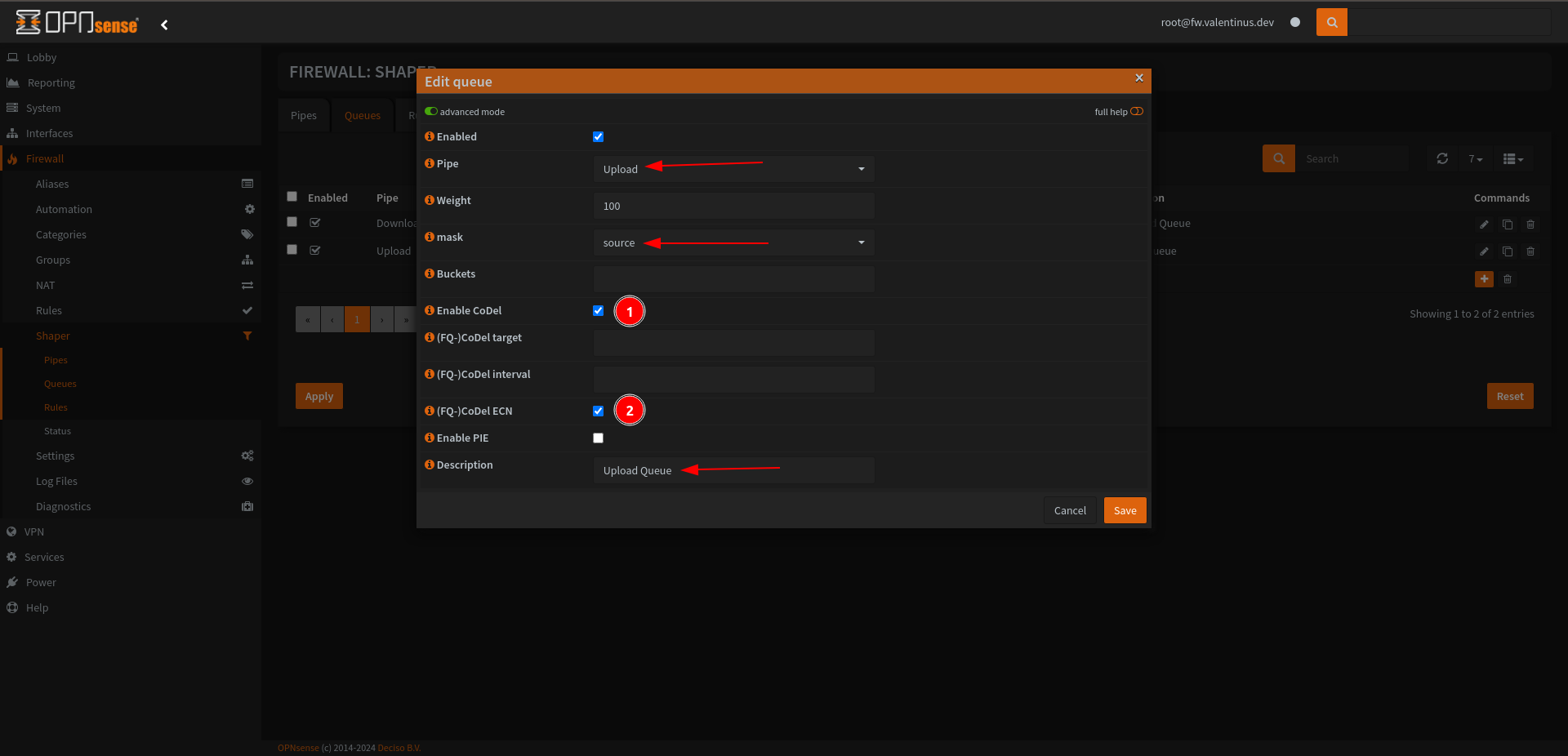
Set Queues
After adding Pipe, the next step is to add Queue, add it as indicated below.
Set:
Enabled: Checked
Pipe: Download
Mask: destination
Enable Codel and (FQ-) Codel
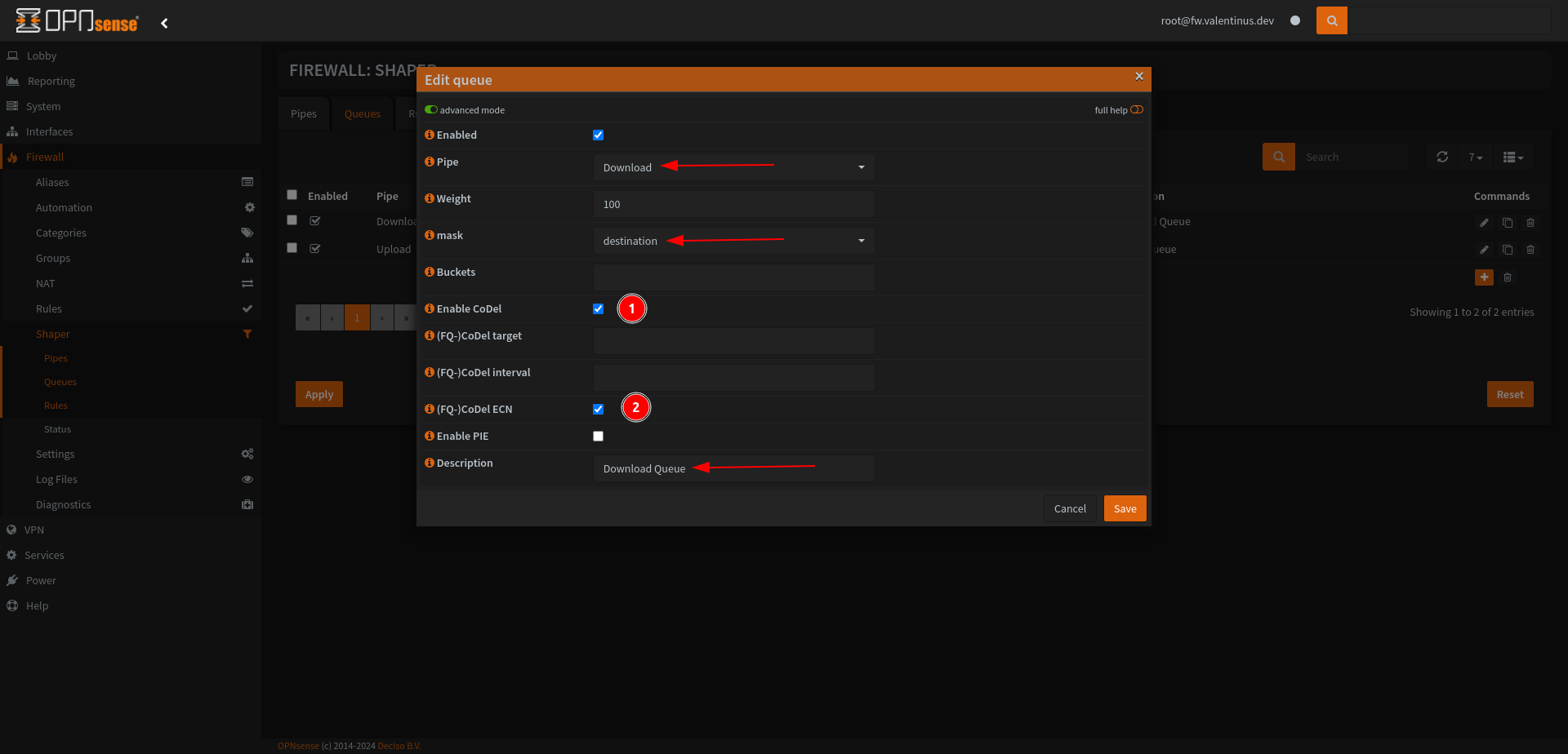
For Upload Queue, most things are the same as above, don’t forget set Pipe: Upload and Mask: source.
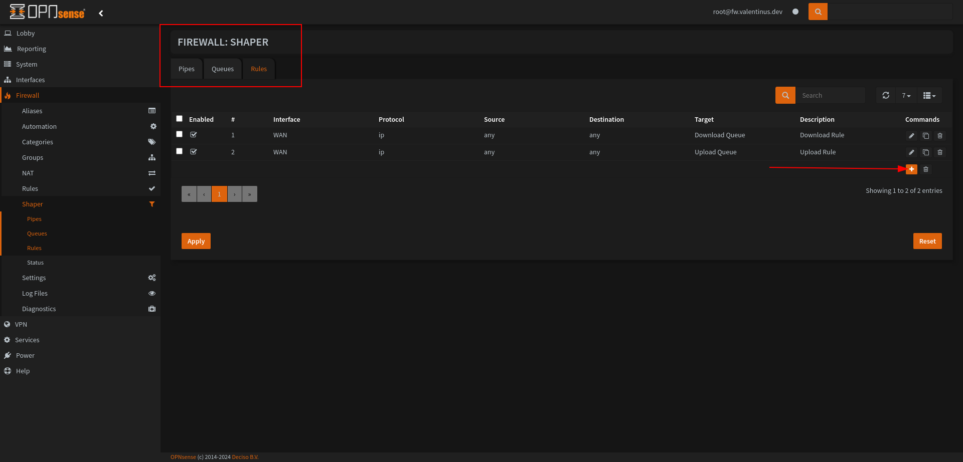
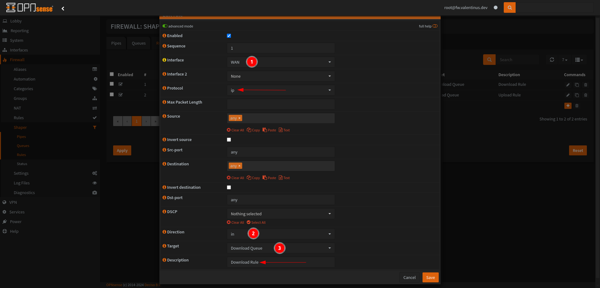
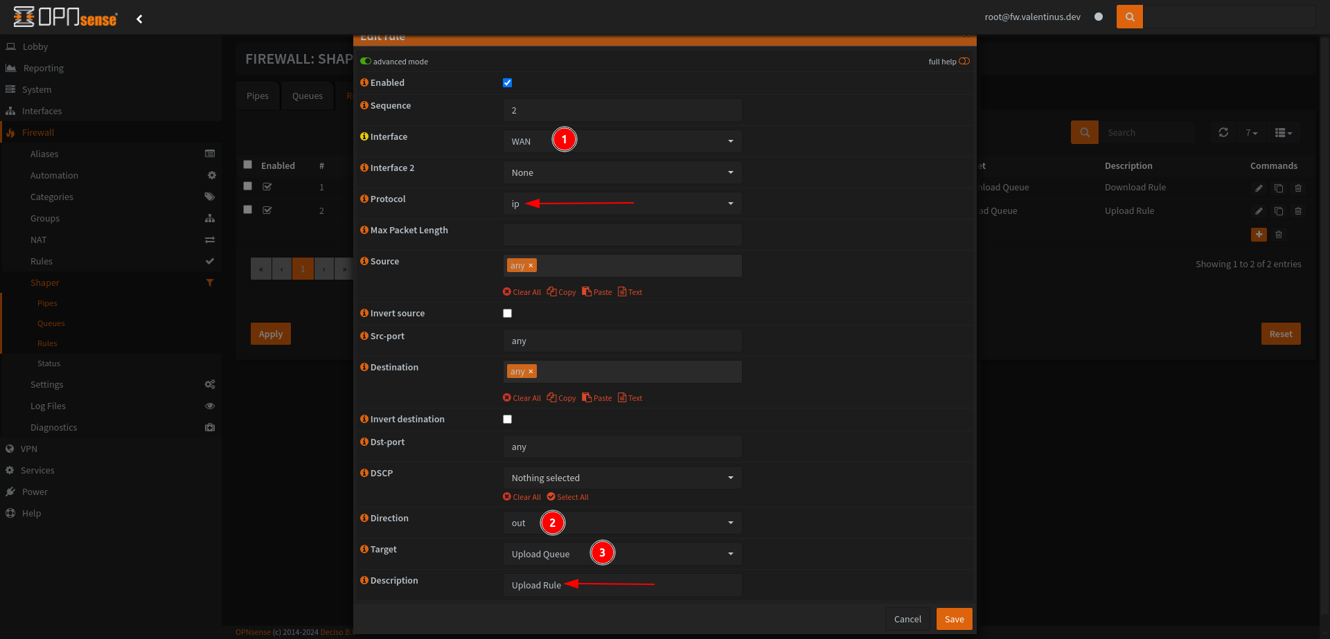
Set Rules
We finish the shaper adjustment part here. Create the rule as described below and then observe the change in your network.
OPNsense Tuning
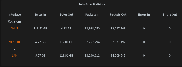
When I observed that the Errors Out value started to increase in the WAN Interface section with Interface Statistics, I realized that I needed to optimize the system.
You can look here for OPNsense Tuning. If you have a 10G NIC, I definitely recommend to take a look.
OPNsense Performance Tuning Guide on Proxmox / Emin’s Notes
I just changed
kern.ipc.maxsockbufto2097152becouse my NIC’s are 1G and testingnet.inet.rss.bitswith2value.
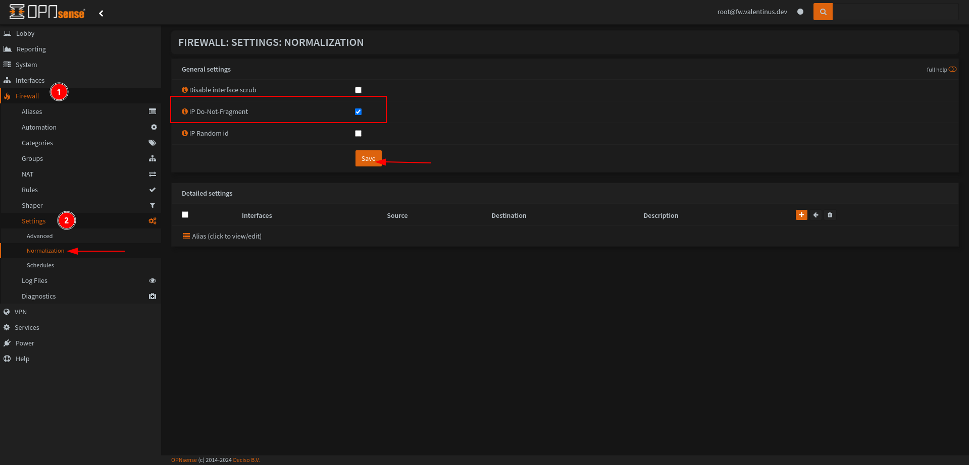
Disable Fragmentation in Firewall --> Settings --> Normalization.
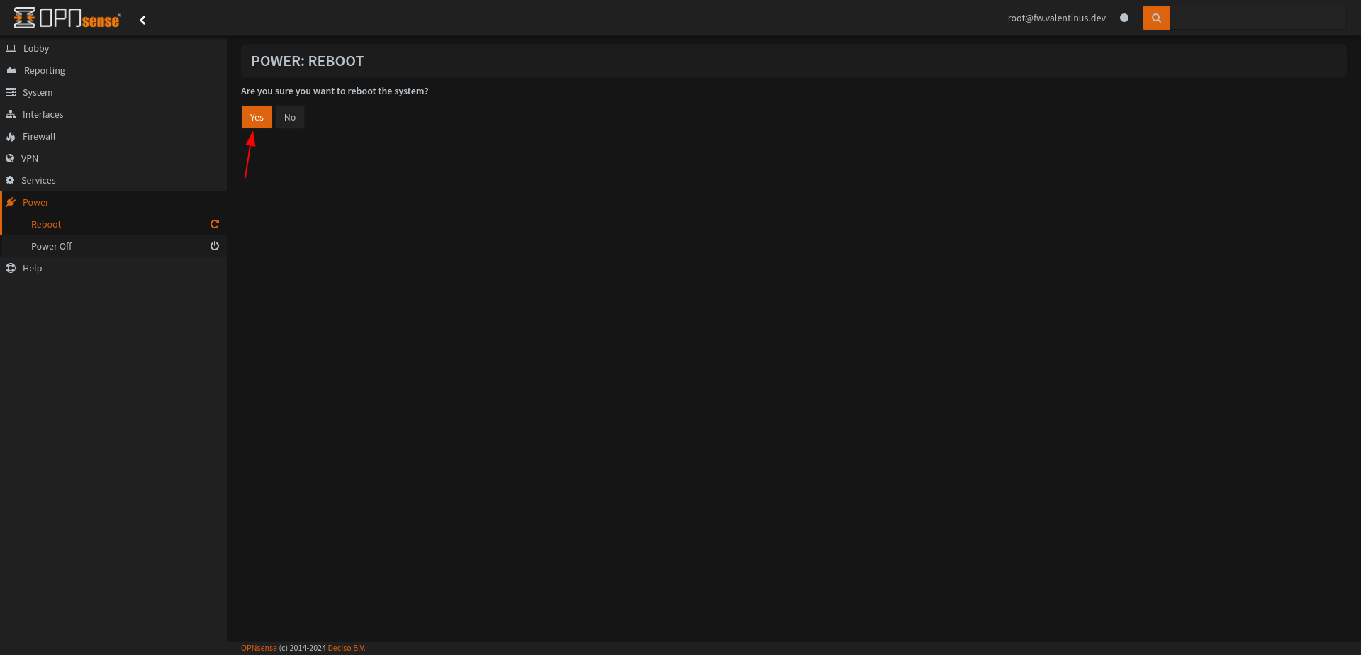
I recommend restarting the Firewall once you have finished setting it up. Otherwise it may cause problems when setting Switch.
Switch Configuration
Connect Switch’s Port 1 to Router LAN and Find Switch’s Local IP
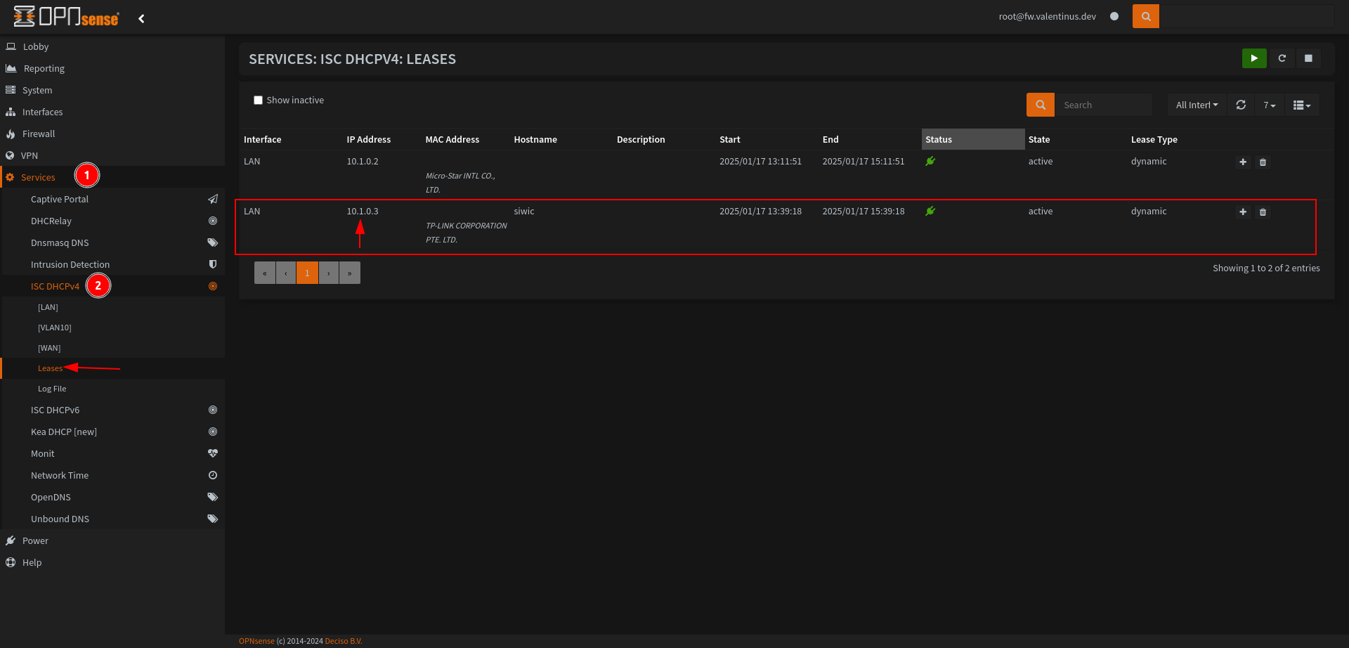
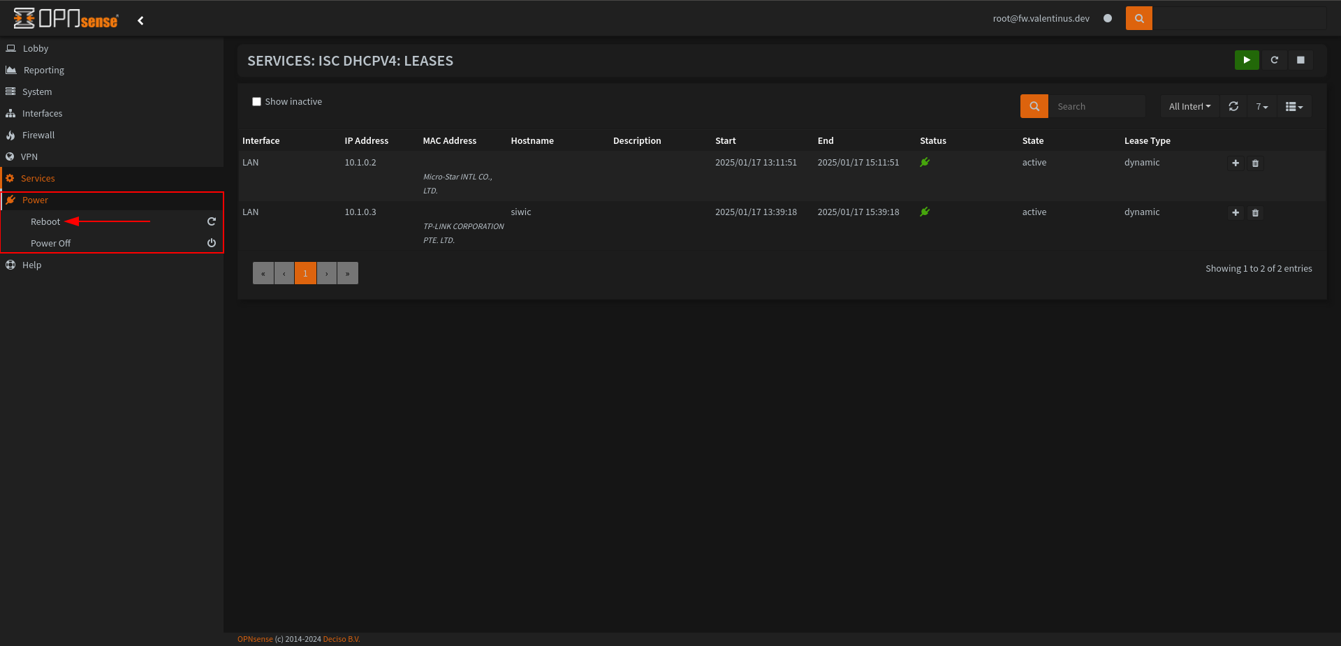
Go to Services --> ISC DHCPv4 --> Leases , when page is load you’ll see MAC Addresses, check this section it’ll show your switch maintainer such as TP-LINK CORPORATION PTE. LTD. .
My switch has 10.1.0.3 address.
Enter 10.1.0.3 from your browser and enter the device’s interface.
802.1Q Settings
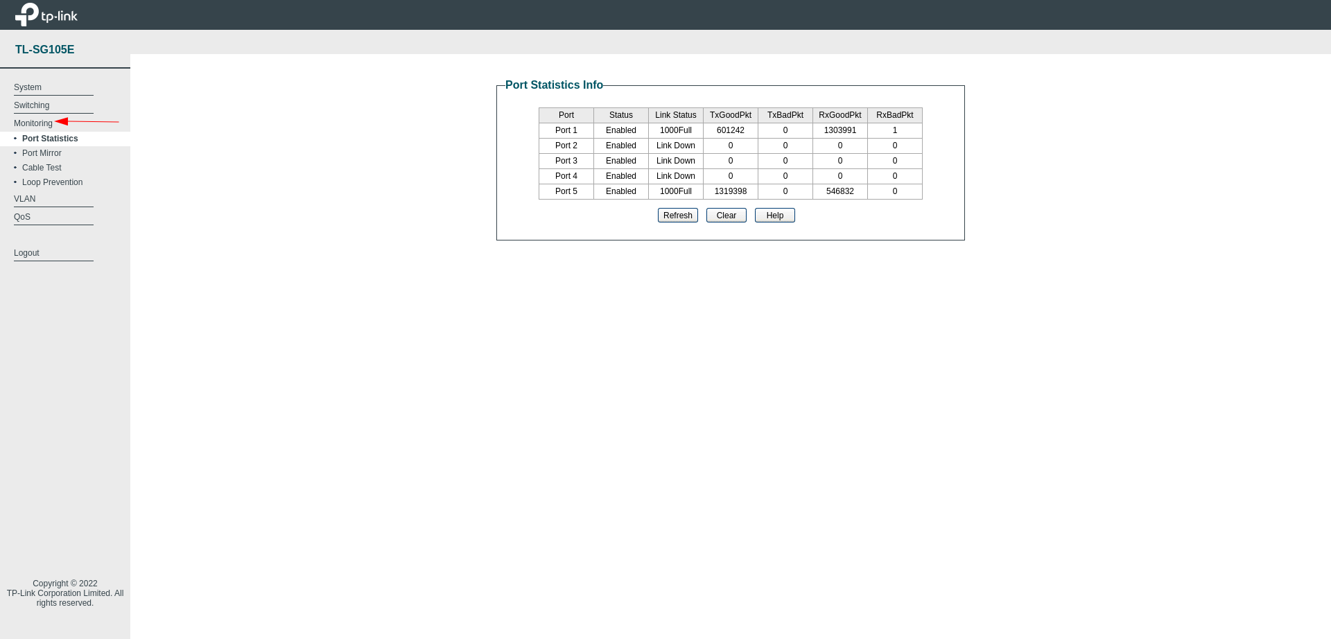
After connecting to the switch, go to Monitoring and check the connected ports.
I connected my own computer to port 5 and it also shows up without any problems.
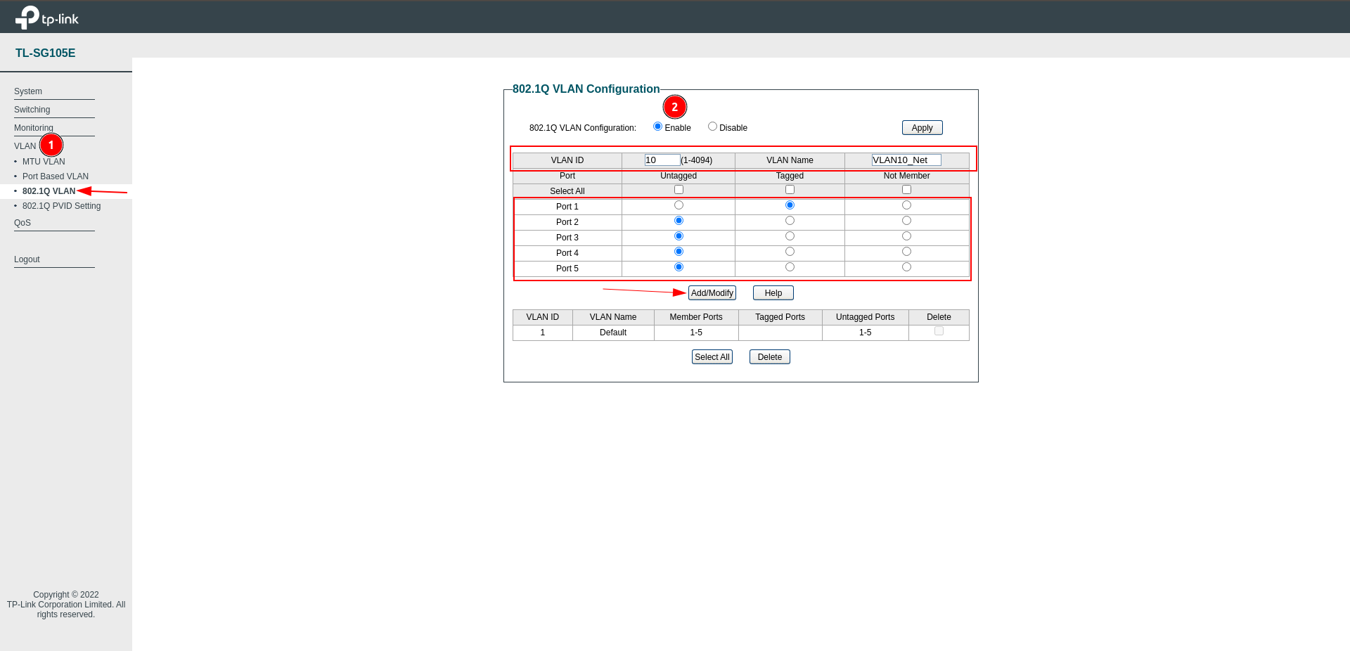
As for the VLAN connection section, go to the 802.1Q VLAN section under VLAN.
After Enabling 802.1Q VLAN Configuration, configure the network as follows, so we have completed the first step of the connection.
VLAN --> 802.1Q VLAN
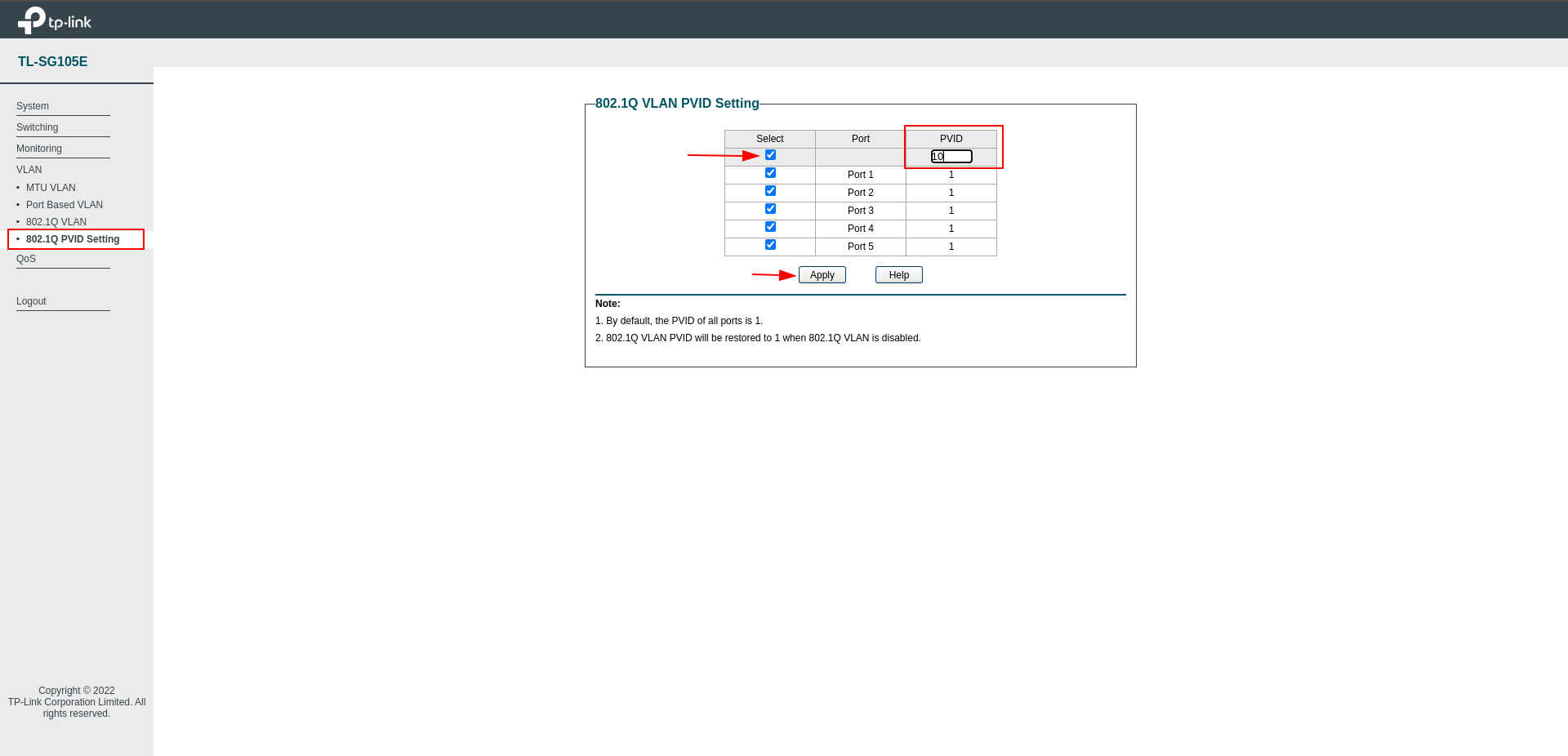
Now we have come to the last part of the VLAN connection, we come to the 802.1Q VLAN PVID section, select all ports and set the PVID to 10.
Thus, the network passing through the Switch will pass through the VLAN.
Since I don’t have a switch that I can manage Layer 3, I restart the Smart Switch I have, so that we can check whether it can receive IP through the Firewall.
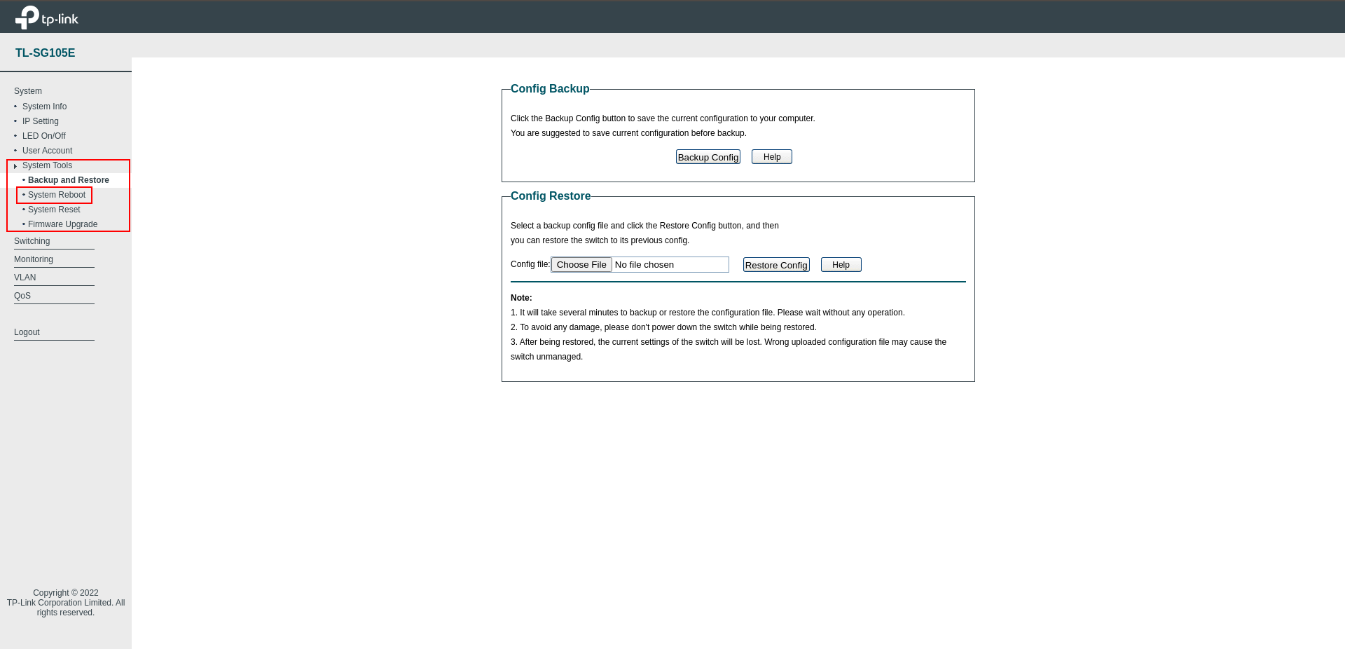
It will be useful to restart the Firewall before making the VLAN connection. In some cases, the Switch cannot receive IP.
Dummy Access Point (WLAN) Configuration
Remove WAN Interfaces and Configuration for Dummy Access Point
We will not need the WAN Interfaces, we delete both of them, and click Save & Apply.
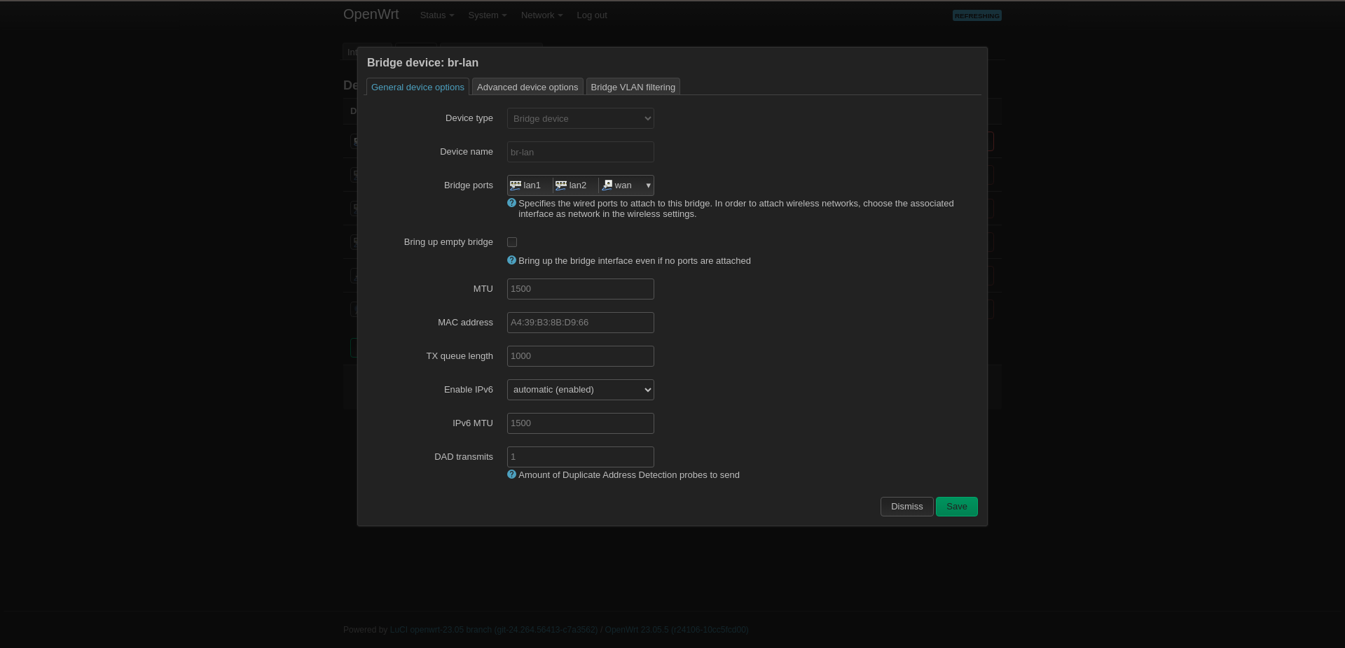
Go to Devices and select Configure to the right of br-lan.
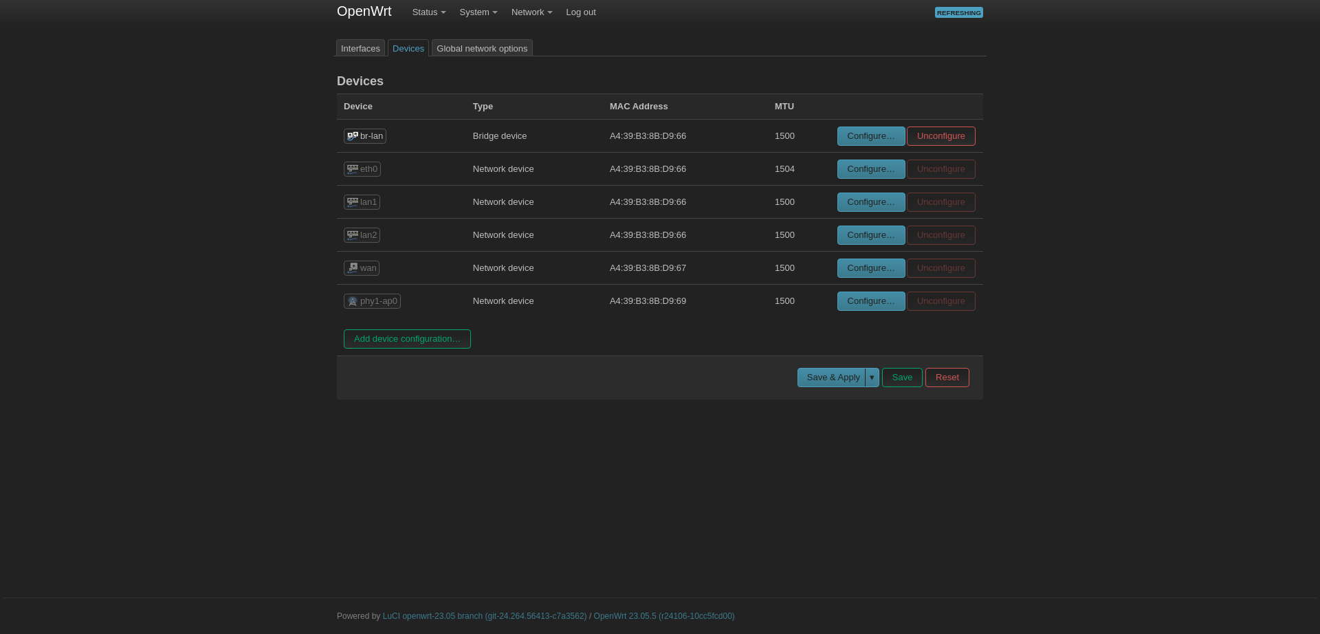
Select Bridge Ports and add the WAN port there. You can connect to the other two ports if you have other access points.
Set Static IP to Access Point
If the Router and Switch settings have been successfully completed, we can now continue from here.
The router I use has OpenWRT in it, and my goal is to turn off DHCP and use it as a WLAN Access Point.
If you have another Router or WLAN Access Point you can use it as a Dummy Access Point or WLAN Access Point.
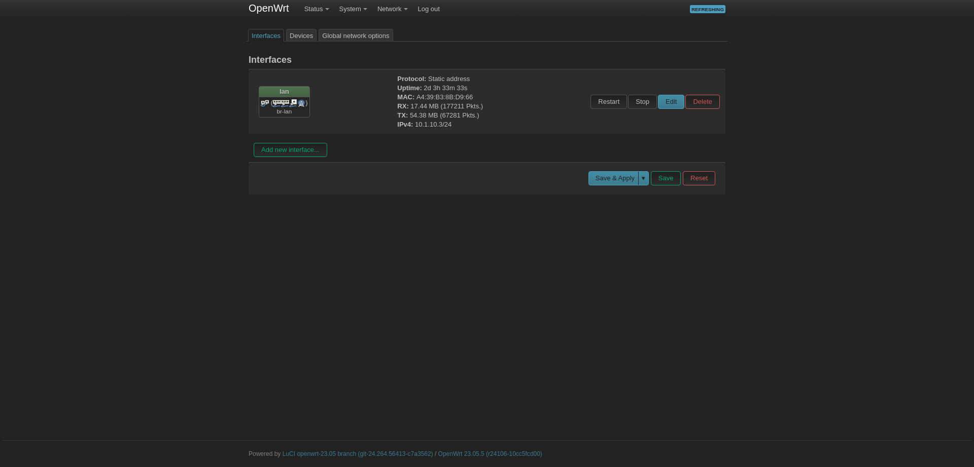
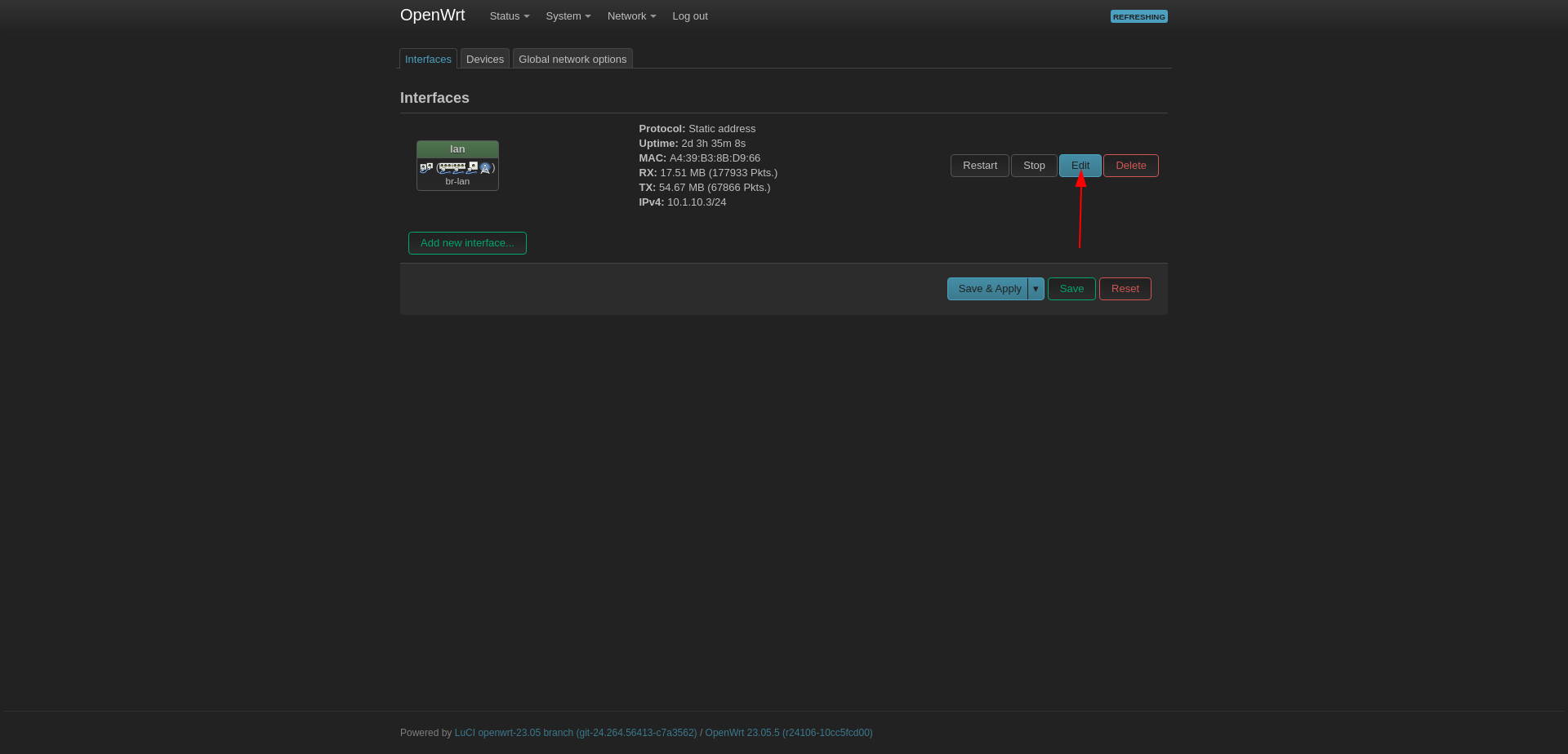
Go to Network --> Interfaces then click to Edit button next to LAN interface.
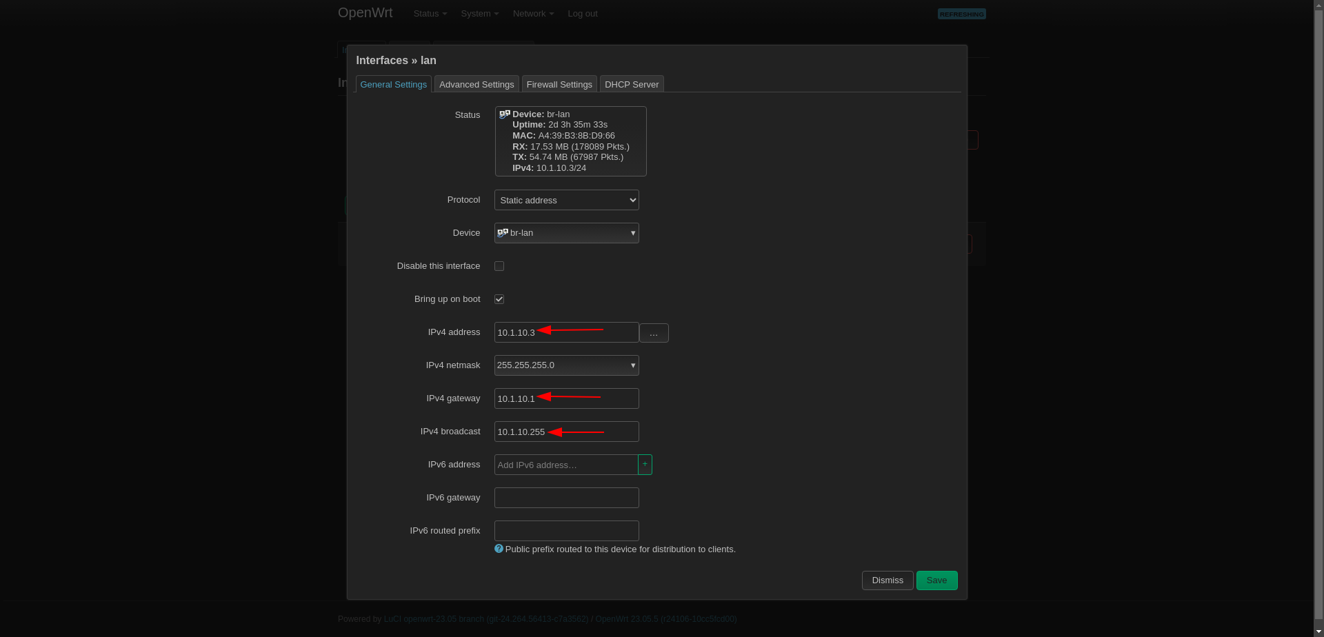
Set:
Protocol: Static Address
IPv4 address: 10.1.10.3
IPv4 netmask: 255.255.255.0
IPv4 gateway: 10.1.10.1 (Firewall VLAN10)
IPv4 broadcast: 10.1.10.255
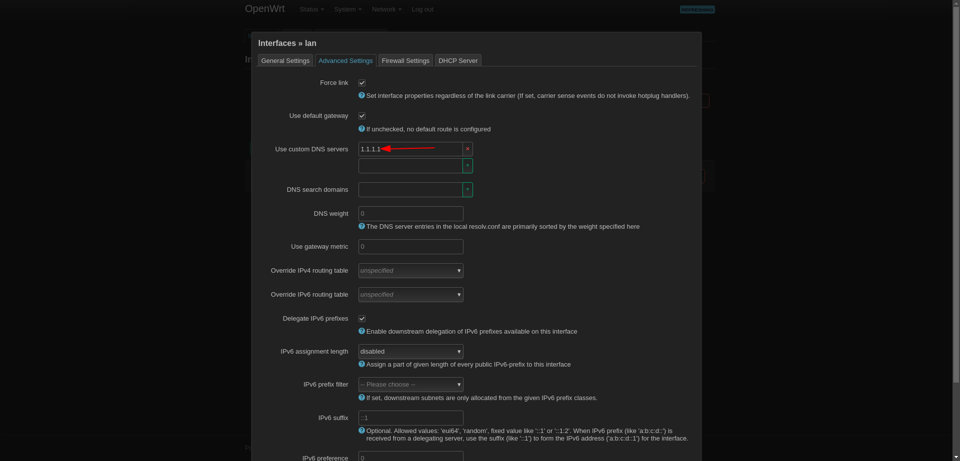
Set DNS Server
Then come to Advanced Settings section and set DNS to 1.1.1.1 or something.
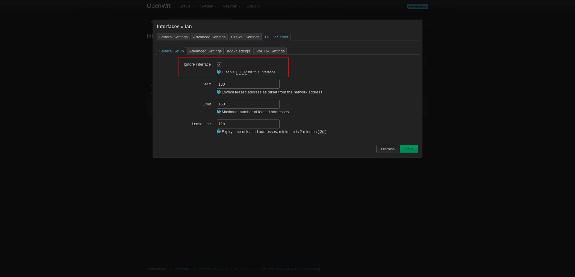
Disable DHCP Server
It comes with DHCP turned on. \
Since we have DHCP turned on in the Firewall, we turn it off here, because if it is turned on here too, the addresses to which the devices will connect may be mismatched.
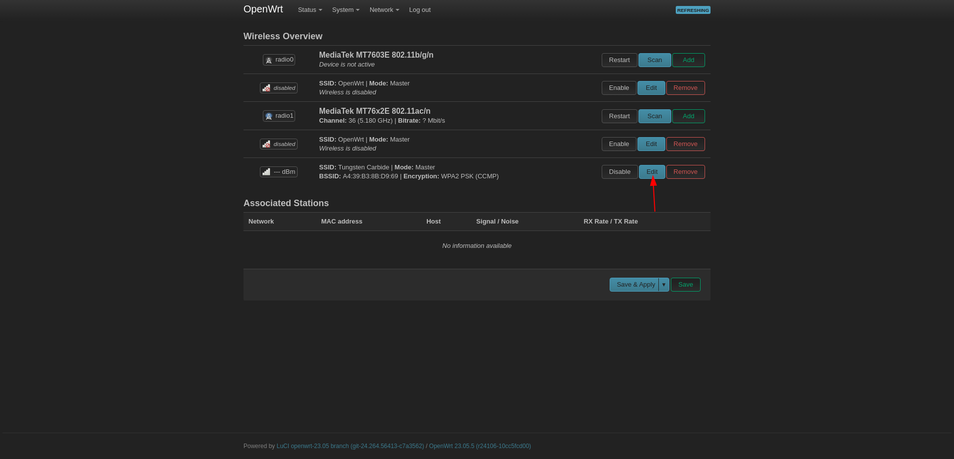
Configuring Wireless
We are nearing the end of setting up the Access Point. Finally, we turn on WLAN.
Go to Network --> Wireless and edit a WLAN network under MediaTek MT76x2E 802.11ac/n .
This is for Wifi5, if you have Wifi6 use ax.
Wireless Security
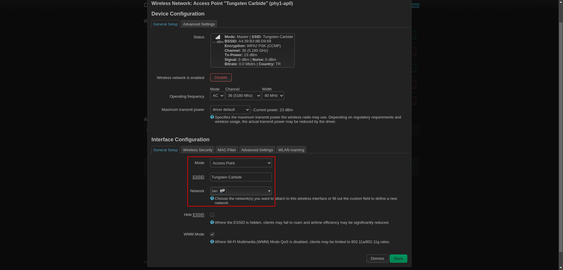
Set:
Mode: Access Point
ESSID: Tungsten Carbide (set it what you want)
Network: LAN
Set:
Encryption: WPA2-PSK
Cipher: Force CCMP (AES)
Then set a wifi password
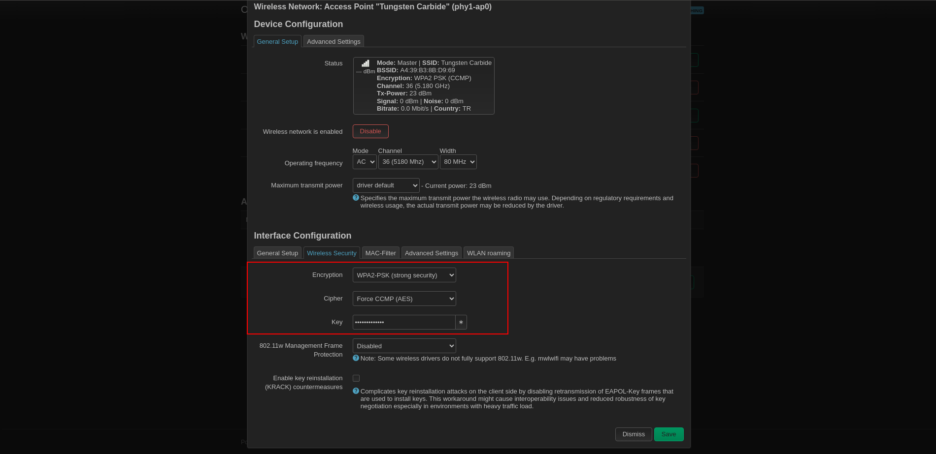
Click Save and click Save & Apply again.
I would like to thank everyone for taking the time to read my article. If you have any questions, feel free to contact me on Linkedin.
Resources
Set Up a Management VLAN for OPNsense, a Network Switch, and a Wireless Access Point / Home Network Guy
OPNsense Performance Tuning Guide on Proxmox / Emin’s Notes
How to Configure VLANs on OPNsense / Zenarmor
VLAN and LAGG Setup / OPNsense Docs
Improve your BufferBloat with Traffic Shaping in Opnsense with IPv6 / Maltech
Fighting Bufferbloat with FQ_CoDel